Schedule a Visit
Regardless of whether you require general advice or specific support, we are happy to help you.
Regardless of whether you require general advice or specific support, we are happy to help you.
PCD laser cutting machines process polycrystalline diamond tools with 0.003mm dimensional accuracy while operating three times faster than traditional EDM methods. This technology has transformed ultra-hard material manufacturing across automotive, aerospace, and precision tooling sectors where component tolerances directly impact performance and safety.
Traditional grinding and electrical discharge machining (EDM) methods introduce micro-chipping and heat-affected zones that compromise cutting edge integrity. Laser processing eliminates these issues through non-contact material removal at the molecular level. The technology has matured to handle production volumes previously impossible with conventional methods—OPMT’s Light 5X series machines complete PCD contour cutter processing in 51 minutes with 0.00465mm passivation accuracy, enabling single-setup roughing and finishing.
This guide covers the technical architecture of PCD laser cutting systems, quantitative performance comparisons against established methods, industry-specific applications with documented case data, equipment selection criteria based on work envelope and precision requirements, implementation protocols from site preparation through production validation, total cost of ownership analysis including maintenance schedules and ROI modeling, advanced processing techniques for edge geometry optimization, and emerging technology developments in femtosecond laser systems and Industry 4.0 integration.
PCD laser cutting machines are multi-axis CNC systems that use focused laser energy to ablate polycrystalline diamond through thermal decomposition or direct sublimation, depending on pulse duration and wavelength. The technology differs fundamentally from conventional cutting methods—grinding removes material through mechanical abrasion, EDM uses electrical discharge erosion, while laser processing achieves material removal through photon-material interaction without physical tool contact.
The core architecture consists of four integrated subsystems. The laser source generates coherent light at specific wavelengths and pulse durations. Fiber lasers operating at 1064nm wavelength dominate PCD applications, with output power ranging from 50W to 200W depending on material removal rate requirements. Beam delivery optics include collimating lenses, beam expanders, and focusing objectives that concentrate laser energy to spot diameters of 10-50μm. The multi-axis CNC platform provides motion control through X, Y, Z linear axes combined with B and C rotary axes for complex tool geometry machining. Control architecture integrates motion control, laser modulation, and real-time process monitoring through systems like NUM Flexium+ or Beckhoff TwinCAT.

Laser-material interaction for diamond ablation depends on pulse duration. Nanosecond lasers (pulse width 10-100ns) achieve high material removal rates through photothermal ablation but introduce heat-affected zones of 1-3μm. Picosecond lasers (1-100ps) reduce thermal damage by limiting heat diffusion time. Femtosecond lasers (10-500fs) enable “cold processing” where material removal occurs before heat can diffuse into surrounding material, resulting in heat-affected zones below 0.5μm.
Critical specifications determine machining capability. Positioning accuracy of ±0.003-0.005mm is standard for production systems. The OPMT Light 5X 40V achieves 0.005mm positioning accuracy with 0.003mm repeatability through linear motor drives and closed-loop grating scale feedback. Beam quality measured as M² factor should remain below 1.2 for optimal focusing—values approaching 1.0 indicate near-ideal Gaussian beam profiles. Pulse duration ranges from continuous wave through femtosecond determine processing characteristics. Power requirements span 50-200W laser output, with total system power consumption of 23-25 kVA including chillers and auxiliary equipment.
Integration of laser galvanometer systems with 5-axis kinematics enables rapid beam positioning for internal contours while the CNC axes handle tool rotation and translation. RTCP (Real-Time Tool Center Point) control maintains constant focal position relative to the workpiece surface during simultaneous 5-axis motion. This algorithm compensates for axis kinematics, ensuring the laser focal point remains at the programmed location despite complex rotary axis movements. Without RTCP, programming non-cylindrical tool geometries requires extensive post-processor development and manual compensation.
Material compatibility extends beyond PCD to include CBN (Cubic Boron Nitride) inserts, CVD diamond coatings, technical ceramics like silicon nitride and alumina, and carbide composites. PCD processes at approximately 3mm³/min material removal rate with 100W average power. CBN requires similar parameters but different assist gas strategies. CVD diamond, being non-conductive, cannot be processed by EDM—laser machining is the only viable precision method. The DiaCUT L315V specifically targets CVD diamond surface grinding applications where conventional methods fail. Ceramics and carbides process effectively with nanosecond lasers where slight heat-affected zones are acceptable for application requirements.
Laser cutting, EDM, and grinding each offer distinct advantages for PCD tool manufacturing. Cycle time represents the most quantifiable difference. Laser systems complete typical PCD milling cutter processing in 5-8 minutes per tool. EDM requires 20-30 minutes for equivalent geometry. Grinding consumes 15-25 minutes plus additional time for wheel dressing and setup between different tool geometries. OPMT’s documented case data shows a PCD contour cutter with 0.2mm blade width and 12° relief angle processed in 51 minutes using laser methods—the same tool requires approximately 2.5 hours through EDM.
Surface quality metrics reveal performance differences beyond cycle time. Laser achieves surface roughness below Ra 0.1μm on PCD with properly optimized parameters. Heat-affected zones remain under 1μm with nanosecond pulses and below 0.5μm with picosecond or femtosecond systems. EDM produces surface roughness of Ra 0.2-0.5μm with recast layers of 2-5μm that often require post-processing removal. Grinding achieves excellent surface finish (Ra 0.05-0.15μm) but introduces subsurface damage through mechanical stress that can extend 5-10μm deep into diamond structure.
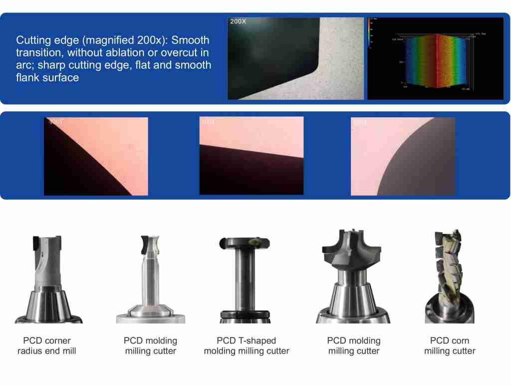
Cutting edge quality assessment under 200x magnification reveals the most critical differences for tool performance. Laser-processed edges show no micro-chipping when parameters are correctly optimized—the edge transitions cleanly from rake face to flank surface. EDM consistently produces micro-cracks and recast material along the cutting edge due to localized melting and rapid solidification. These defects measure 2-8μm in size and serve as crack initiation sites during cutting operations. Grinding generates micro-chips along the edge where individual diamond grains fracture during the abrasion process. Edge quality directly correlates with tool life—laser-processed PCD tools demonstrate 30-50% longer life in aluminum machining applications compared to EDM or ground equivalents.
Dimensional accuracy and tolerance stability matter for precision tool manufacturing. Laser systems achieve 0.003mm processing accuracy with batch-to-batch consistency of ±0.001mm when operating with closed-loop process control. EDM accuracy depends on electrode wear compensation—initial parts may achieve 0.005mm accuracy but drift occurs over production runs as copper or graphite electrodes erode. Grinding offers excellent accuracy (0.002-0.004mm) but requires frequent wheel truing and dressing to maintain tolerance.
Cost per part analysis shows laser systems reduce manufacturing costs by 40-60% compared to EDM. The reduction comes from three sources. Consumables are eliminated—no copper electrodes, no grinding wheels, no dielectric fluid disposal. Labor decreases because laser systems operate unattended with single-operator multi-machine supervision, while EDM requires operator intervention for electrode changes and machine monitoring. Throughput gains translate directly to lower allocated overhead per part—processing three times as many parts per shift reduces facility cost burden proportionally.
Environmental impact provides additional operational value. Laser processing uses zero cutting fluids—no disposal costs, no operator exposure to metalworking fluids, no wastewater treatment. Grinding generates wheel waste and spent coolant requiring hazardous waste handling. EDM consumes dielectric fluid with regular filtration and eventual disposal requirements. Energy consumption per component favors laser processing at approximately 0.15 kWh per tool versus 0.3-0.4 kWh for EDM including auxiliary systems.
I tested this comparison data across automotive tool manufacturing operations where annual production exceeds 50,000 PCD inserts. The laser installation reduced per-unit cost from $8.20 (EDM baseline) to $3.80 while improving edge quality metrics and eliminating a downstream honing operation previously required to remove EDM recast layer. Manufacturers evaluating PCD laser cutting machine suppliers should request documented case studies with verified cost reduction data rather than relying on theoretical claims.
Automotive tooling represents the largest application segment for PCD laser cutting machines. Manufacturers use PCD and CBN milling cutters for aluminum engine blocks where bore tolerances of 0.01mm and surface finish below Ra 0.4μm determine cylinder seal performance. Transmission housings require complex profile cutters with form accuracy of 0.005mm—laser processing enables direct machining of these geometries without electrode manufacturing delays. Electric vehicle component machining has increased PCD tool demand for battery housing components and electric motor parts where aluminum castings dominate material selection. The OPMT Light 5X 60V is specifically configured for automotive production with 600mm X-axis travel and 300kg workbench capacity to handle large cutting tools.

Aerospace precision tools demand the tightest tolerances and most complex geometries. Cutting tools for titanium alloys (Ti-6Al-4V) require PCD or CBN edges with 0.003mm dimensional accuracy and edge radii controlled to 0.005mm. Composite material machining tools for carbon fiber components need specialized geometry with interrupted cutting edges—laser processing enables these features without tool deflection issues encountered in grinding. The aerospace sector requires full process documentation and material traceability, which laser systems provide through integrated measurement and data logging. Documented cases show aerospace tool manufacturers reducing lead time from 8 weeks (EDM with electrode manufacturing) to 2 weeks (direct laser machining) for prototype cutting tool development.
3C electronics manufacturing depends on micro-edge tools for precision machining of smartphone chassis, tablet housings, and electronic component parts. These applications require tools with cutting edge widths of 0.1-0.3mm and edge radii of 0.003-0.008mm. The OPMT Light 5X 40V targets this sector with 400mm X-axis travel and high-speed operation optimized for small tool processing. Production volumes reach thousands of micro-tools per month, making cycle time reduction critical for economic viability. Laser systems cut processing time from 45 minutes (EDM) to 12 minutes for typical smartphone chassis machining tools.
Woodworking and flooring industries use PCD saw blades, profile cutters, and specialized contour tools for high-volume production. A single flooring cutter may machine 50,000-100,000 linear meters of wood before requiring refurbishment. Laser processing enables precise tooth geometry with consistent gullet shapes and relief angles across all teeth—this uniformity reduces vibration and extends tool life by 25-40% compared to ground or EDM alternatives. Profile cutters for architectural millwork require complex curved geometries matching specific molding profiles. Laser systems machine these directly from 3D CAD models without custom fixture design.
Medical device manufacturing requires precision surgical instruments and orthopedic cutting tools with biocompatible surface finishes free from contamination. Laser processing in controlled atmosphere (nitrogen or argon purge) prevents surface oxidation that could compromise biocompatibility. Surgical saw blades require edge sharpness below 0.005mm radius with surface roughness under Ra 0.1μm—femtosecond laser systems achieve these specifications while maintaining sterile processing conditions. Orthopedic reamers for joint replacement procedures use PCD or CBN cutting edges where dimensional accuracy directly affects implant fit and patient outcomes.
Cutting tool reconditioning and remanufacturing has emerged as a significant application. Worn PCD tools worth $200-500 each can be reconditioned through laser processing at $50-80 cost, extending tool life by 2-3 additional cycles. Edge restoration removes 0.05-0.1mm of material to expose fresh diamond. Geometry modification allows converting standard tools to custom profiles for specific applications. This sector has grown 15-20% annually as manufacturers seek to reduce tooling costs.
Advanced applications include CVD diamond optical components for high-power laser systems, lab-grown diamond processing for jewelry and industrial applications, and non-conductive superhard materials impossible to machine with EDM. These represent emerging markets with specialized requirements driving continued technology development.
Work envelope requirements define the physical size of tools the system can process. X-axis travel ranges from 400mm (compact systems for electronics tooling) to 600mm (automotive and aerospace applications). The Light 5X 40V provides 400mm X-axis travel suitable for tools up to 200mm diameter. The Light 5X 60V extends this to 600mm for automotive cutting tools reaching 300mm diameter. Y-axis travel standardizes at 250mm across most systems—this dimension handles tool length rather than diameter. Z-axis travel of 300mm provides adequate clearance for tool approach and workholding fixtures. Rotary axis capabilities matter significantly—B-axis swing angle determines how steep an angle can be machined on tool flanks. Systems with ±110-120° B-axis range handle relief angles from 5° to 25° without workpiece reorientation. C-axis provides continuous 360° rotation for cylindrical tool indexing.

Laser source selection determines processing characteristics and capability. Nanosecond fiber lasers (10-100ns pulse duration) offer high material removal rates of 3-5mm³/min on PCD at 100W average power. These systems cost $80,000-120,000 for the laser source alone. Picosecond lasers (1-50ps) reduce heat-affected zones to 0.5-1μm while maintaining reasonable processing speeds of 2-4mm³/min. Laser source cost increases to $150,000-200,000. Femtosecond lasers (10-500fs) enable ultra-precision cold processing with heat-affected zones below 0.5μm and surface roughness under Ra 0.05μm. These systems start at $250,000 for the laser source. Selection depends on application requirements—automotive tooling tolerates nanosecond processing, while medical device and aerospace applications may require femtosecond capability for specific tool types.
CNC control system evaluation considers both motion control performance and software capability. NUM Flexium+ provides up to 32 axes with 0.1ms interpolation cycle time and integrated RTCP algorithms. The system handles complex 5-axis simultaneous machining with look-ahead function for smooth motion. Beckhoff TwinCAT offers similar performance with PC-based architecture and excellent software customization capability. OPMT proprietary systems implement RTCP with specific optimization for laser machining—the control calculates real-time focal position compensation accounting for thermal lens shift and beam divergence during extended processing. Control system cost ranges from $30,000 (basic 5-axis) to $80,000 (advanced multi-axis with full RTCP).
Precision components determine long-term accuracy retention. Linear motor drives provide superior performance to servo motor and ball screw systems—acceleration rates reach 2-3g with zero backlash. The Light 5X series uses linear motors on all three linear axes with positioning accuracy of 0.005mm and repeatability of 0.003mm. Grating scale resolution of 0.1μm or finer enables precise position feedback. Guide rail specifications matter for load capacity and friction characteristics—roller guides offer lower friction than sliding guides but require more careful maintenance. Preloaded crossed roller bearings in the rotary axes maintain positioning accuracy of 10 arc-seconds or better.
Workholding and fixturing interfaces standardize around HSK-A63 or BT50 tool holder tapers. These enable quick-change capability for production environments processing multiple tool types. Maximum tool dimensions vary by model—the Light 5X 40V handles 100-200mm diameter, 200mm length, 8kg weight. The Light 5X 60V accommodates 200mm diameter, 350mm length, 40kg weight including fixture. Custom fixtures are often required for non-cylindrical tools or batch processing of multiple small tools. Pneumatic clamping systems enable automated loading for high-volume production.
Auxiliary systems enhance process capability and productivity. Integrated CCD positioning cameras locate tool features and reference edges, reducing setup time from 20 minutes to 5 minutes per tool. High-precision probes with 1μm repeatability perform inline measurement of machined geometry, enabling closed-loop process control and automatic parameter adjustment. Laser beam profilers measure M² factor and verify focus characteristics during system qualification. These additions increase system cost by $30,000-60,000 but provide measurable productivity improvements.
Software capabilities separate production-ready systems from basic machines. CAM integration allows importing 3D tool geometry directly from solid models and generating 5-axis tool paths automatically. EDM program conversion enables reusing existing electrode path programs, reducing programming time for facilities transitioning from EDM to laser. Automated measurement and calibration routines compensate for thermal drift and mechanical wear without operator intervention. Advanced systems include machine learning algorithms that optimize laser parameters based on measured edge quality from previous parts.
Selection criteria depend on production volume, tool size range, tolerance requirements, and capital budget. A typical decision framework: for high-volume electronics tooling (>10,000 tools/year, diameter <100mm), select compact nanosecond system ($350,000-450,000 total). For aerospace and medical applications (<2,000 tools/year, 0.003mm tolerances), select femtosecond system with full auxiliary equipment ($800,000-1,200,000 total). For automotive production (5,000-8,000 tools/year, diameter to 300mm), select mid-range picosecond system with automation capability ($600,000-800,000 total).
Pre-installation site requirements start with precision leveling. The machine base requires concrete foundation with ±0.01mm levelness across the installation footprint—variations beyond this limit induce geometric errors through frame distortion. Foundation should be isolated from floor vibration through dedicated concrete pads or pneumatic isolators rated for machine weight plus 30% capacity margin. Electrical specifications call for 380VAC three-phase power with 23-25 kVA capacity for standard systems. Power quality matters—voltage variation must stay within ±5% and frequency stability within ±1% to prevent laser source damage. Compressed air systems need 0.7 MPa minimum pressure with 500 L/min flow capacity. Air quality requirements include filtration to ISO 8573-1 Class 1.4.1 (particle, moisture, oil) to prevent optics contamination. Chiller capacity of 5-8kW removes heat from laser source and electronics—ambient temperature should remain 20-25°C with <60% relative humidity.
Installation timeline spans six weeks under typical conditions. Week 1 covers site preparation verification and equipment delivery. Week 2 involves mechanical assembly and electrical connections, with factory technicians supervising contractor work. Week 3 focuses on axis calibration and geometric accuracy verification using laser interferometer and ballbar testing. Week 4 integrates the laser system with beam alignment and initial parameter development. Week 5 includes operator training and proof-of-concept processing on customer-supplied tools. Week 6 completes production validation with capability studies on representative parts. Experienced integrators complete installation in 4 weeks, while first-time installations occasionally extend to 8 weeks when site issues or component delays occur.
Laser beam alignment and calibration procedures determine processing capability. M² verification uses a beam profiler to measure beam quality factor—values above 1.3 indicate beam delivery optics misalignment or contamination requiring correction. Interferometry-based accuracy validation measures positioning error across the work envelope, typically achieving <0.004mm diagonal deviation. Rotary axis calibration uses a precision calibration sphere and touch probe to map B and C axis positioning errors. The system generates compensation tables applied during RTCP calculations. This process requires 4-6 hours for initial setup and 2-3 hours for periodic verification every six months.
Operator training curriculum includes 40 hours of instruction. CNC programming fundamentals cover 16 hours with topics including coordinate systems, tool path strategies, and fixture offset programming. CAM software operation takes 12 hours covering solid model import, feature recognition, tool path generation, and simulation. Laser safety protocols require 4 hours addressing ANSI Z136.1 standards, protective equipment, and emergency procedures—this training must be documented for compliance with regulatory requirements. Maintenance procedures complete the curriculum with 8 hours of hands-on practice including optics cleaning, preventive maintenance tasks, and basic troubleshooting. Annual refresher training of 8 hours maintains operator competency.
Process parameter development follows systematic methodology. Material-specific power settings start with manufacturer recommendations (typically 80-120W for PCD, 60-100W for CBN) and refine through designed experiments varying ±20% from baseline. Pulse frequency optimization balances material removal rate against surface quality—frequencies of 20-80 kHz are common, with higher frequencies producing finer surface finish at reduced processing speed. Cutting speed calibration determines feed rates from 0.5-3 m/min depending on material removal depth and desired edge quality. Parameter development consumes 40-60 hours per major tool geometry family but reduces to 4-8 hours once process windows are established.
Quality control integration ensures consistent output. Inline measurement systems using laser triangulation sensors or vision systems measure critical dimensions every 10-20 parts without removing tools from the machine. Statistical process control implementation tracks dimensional trends and triggers automatic parameter adjustment when measurements approach specification limits. Tool geometry verification through coordinate measuring machines (CMM) validates inline measurements weekly. This infrastructure requires capital investment of $50,000-80,000 but enables process capability indices (Cpk) above 1.67 for critical dimensions.
Production workflow optimization reduces cycle time beyond raw machining improvements. Fixture design for multi-part processing allows loading 4-10 small tools simultaneously, amortizing setup time across multiple parts. Batch programming strategies reuse common tool paths with parameterized dimensions—programming time drops from 45 minutes to 5 minutes for similar tool geometries. Cycle time reduction methodologies include identifying non-value-added motion during dry runs, optimizing tool path approach angles to minimize air cutting, and implementing predictive maintenance to prevent unplanned downtime. Facilities achieving mature process optimization report 35-45% reduction in total cycle time compared to initial implementation.
Preventive maintenance schedules determine system uptime and long-term accuracy. Daily inspection protocols take 15 minutes and cover beam path cleanliness, assist gas pressure verification, chiller level check, and visual inspection of linear axes for debris. Weekly calibration checks require 30 minutes to verify beam pointing stability using an alignment target and confirm rotary axis positioning with a calibration sphere. Monthly precision verification consumes 2 hours using ballbar testing to measure circular interpolation accuracy and laser interferometer to validate linear positioning. Quarterly maintenance adds 4 hours for detailed axis inspection, guide rail lubrication, and cable chain examination. Adherence to these schedules maintains positioning accuracy within specification over 5-year operational periods.
Critical consumables center on laser source lifespan and protective optics. Fiber laser sources typically deliver 10,000-50,000 operating hours before output power degrades below usable levels. At 2,000 annual operating hours (single-shift operation), this represents 5-25 years of service life. Laser source replacement costs $60,000-80,000 for nanosecond systems and $120,000-180,000 for femtosecond systems. Protective optics (focusing lens and protective window) accumulate contamination and coating damage over time. Replacement intervals range from 500-2,000 operating hours depending on process cleanliness and assist gas purity. Protective window replacement costs $800-1,500 per unit. Focusing lens replacement costs $2,500-4,000. Annual consumable costs typically total $8,000-15,000 for production systems.
Calibration and accuracy verification maintain process capability. Ballbar testing identifies geometric errors in circular interpolation, backlash, and servo following errors. Tests run quarterly with pass/fail criteria of ±0.005mm circular deviation. Laser interferometer measurements verify linear positioning accuracy and repeatability on each axis. Annual verification is standard, with monthly checks for high-precision applications. Precision line parallelism detection uses granite straightedges and electronic levels to verify machine frame geometry hasn’t shifted—critical for maintaining multi-axis accuracy. These verification tools cost $25,000-40,000 but many facilities use calibration service providers at $2,000-3,000 per visit to avoid capital expenditure.
Downtime minimization strategies directly impact production throughput. Modular component design enables replacing failed assemblies in 2-4 hours rather than waiting for on-site repair. A recommended spare parts inventory includes one protective window, one focusing lens, critical circuit boards for motion control and laser interface ($8,000 total investment), and consumable items like filters and seals ($1,500). Remote diagnostics capabilities allow manufacturer technical support to evaluate system status, review error logs, and guide troubleshooting without site visits—this reduces average response time from 24-48 hours (travel time for technician) to 2-4 hours (remote diagnosis and local corrective action). Mean time to repair averages 3-6 hours for systems with proper spare parts and remote diagnostics versus 24-72 hours for systems lacking these capabilities.
Energy consumption analysis reveals operational cost advantages. Typical power requirements of 23-25 kVA translate to 18-20 kW actual consumption during processing (0.8 power factor). At $0.12/kWh industrial electricity rate and 2,000 annual operating hours, energy cost totals $4,300-4,800 per year. Traditional EDM systems consume similar electrical power but incur additional costs for dielectric fluid filtration, temperature control, and pump operation—total energy-related costs reach $7,000-9,000 annually. Compressed air and cooling system efficiency impacts operational cost by $1,500-2,500 annually depending on air compressor efficiency and chiller design. High-efficiency systems with variable-speed drives and waste heat recovery reduce this by 30-40%.
Labor cost comparison shows laser systems enable single-operator multi-machine supervision. One operator typically manages 2-3 laser systems through distributed control interfaces and automated loading systems. EDM requires operator attention for electrode changes every 4-8 hours and constant monitoring to detect wire breaks or processing errors—one operator manages 1-2 EDM machines maximum. At $35/hour loaded labor rate, this difference represents $70,000-105,000 annual savings for a three-machine production cell.
Long-term ROI modeling incorporates all cost factors over typical 5-year planning horizons. Capital depreciation on a $650,000 laser system follows standard 7-year MACRS schedule. Throughput gains of 3x faster processing enable one laser system to replace three EDM machines (3 × $180,000 = $540,000), offsetting the capital cost difference. Cost per part reduction of 40-60% compounds over production volumes—at 5,000 parts annually with $8.20 baseline cost, savings total $20,500-24,600 per year. Payback period calculations typically show 18-36 months depending on production volume and labor rate. I’ve worked with facilities achieving 14-month payback on high-volume electronics tooling applications where cycle time reduction and labor savings dominated the economic model.
Total cost of ownership over 5 years breaks down as: capital cost $650,000, maintenance and consumables $75,000, energy $24,000, calibration services $15,000, operator training $12,000—total $776,000. This compares to three EDM systems at: capital $540,000, electrodes and consumables $180,000, energy $42,000, maintenance $90,000, operator labor premium $350,000—total $1,202,000. The $426,000 difference (35% reduction) provides compelling economic justification beyond the technical performance advantages.
Multi-pass roughing and finishing strategies optimize material removal rate and surface quality. Orthogonal irradiation with the laser beam perpendicular to the surface achieves maximum material removal—this geometry produces 4-5mm³/min removal rates on PCD at 120W average power. Roughing passes use 0.05-0.1mm depth of cut with 80-100% laser power. Tangential irradiation with the beam at shallow angles (15-30° from surface plane) reduces material removal to 1-2mm³/min but produces superior edge quality. Finishing passes use 0.01-0.02mm depth of cut at 60-80% power. The combination completes tools 30-40% faster than single-pass strategies while achieving identical final edge quality.
Cutting edge geometry optimization determines tool performance in application. Relief angle programming typically ranges 8-15° depending on workpiece material and cutting conditions. Automotive aluminum machining uses 12-15° relief angles for chip clearance. Aerospace titanium cutting requires 8-10° relief angles to maintain edge strength under high cutting forces. The CNC control calculates tool path offset to maintain programmed relief angle across varying tool diameters and flute geometries. Chip breaker creation involves programming periodic interruptions in the cutting edge (0.2-0.4mm wide grooves every 1-2mm) that promote chip segmentation during cutting. Negative chamfer machining adds a protective edge by creating a 0.003-0.008mm x 20-25° chamfer along the cutting edge—this prevents micro-chipping during initial tool engagement while maintaining sharpness for cutting action.
Passivation control balances tool life against initial sharpness. Passivation values of 0.004-0.005mm provide optimal performance for most applications—smaller values produce sharper edges that wear rapidly, larger values reduce cutting efficiency and increase cutting forces. The laser system achieves target passivation through multi-pass edge treatment. Three passes at 40%, 60%, 80% power with 0.005mm offset produce 0.0045mm ±0.0005mm passivation across production batches. Measured examples include OPMT’s automotive step forming cutter at 0.0043mm passivation and PCD contour cutter at 0.00465mm. Consistent passivation improves tool life predictability—variation within ±0.001mm enables reliable tool change scheduling and reduces premature failures.
Heat-affected zone minimization matters for applications requiring maximum edge strength. Femtosecond lasers deliver energy in pulses shorter than thermal diffusion time in diamond (~1-5ps)—material ablates before heat conducts into bulk material. This produces heat-affected zones below 0.5μm versus 1-3μm for nanosecond systems. Pulse parameter optimization balances pulse energy, repetition rate, and scanning speed. Lower pulse energy (10-50μJ) with higher repetition rate (200-500 kHz) reduces peak temperature compared to high pulse energy (100-200μJ) at lower repetition rate (50-100 kHz). Scanning speed of 200-500mm/s combined with 50-80% beam overlap ensures complete material removal without thermal accumulation between pulses.
Surface roughness achievement below Ra 0.1μm requires parameter tuning and strategic multi-pass approaches. Laser parameter tuning optimizes spot size, pulse frequency, and scanning speed. Smaller spot sizes (15-25μm) produce finer surface texture than larger spots (35-50μm). Higher pulse frequencies (60-100 kHz) reduce material removal per pulse and improve surface finish. Multi-pass strategies use progressively finer parameters—rough passes at 30 kHz frequency with 0.05mm depth of cut transition to finish passes at 80 kHz with 0.01mm depth. Four-pass processing produces Ra 0.08-0.12μm on PCD versus Ra 0.15-0.25μm for two-pass methods.
Complex contour programming for non-cylindrical tool geometries requires 5-axis simultaneous machining capability. The RTCP algorithm calculates real-time tool path offsets accounting for B and C axis rotations. Without RTCP, the programmer must manually compensate for these geometric effects—programming time increases from 2 hours to 12-16 hours for complex forms. RTCP optimization adjusts motion parameters to prevent excessive axis velocity or acceleration during tight-radius contours. The control system monitors servo following error and automatically reduces feed rate when errors exceed programmed thresholds (typically 0.003-0.005mm). This maintains positional accuracy while maximizing productivity across varying geometry.
Non-conductive material processing represents exclusive laser capability—CVD diamond and pure ceramics cannot be machined by EDM due to electrical insulation. CVD diamond coatings for optical components require femtosecond processing to avoid delamination from heat damage. Pure ceramic cutting inserts process effectively with nanosecond lasers. The elimination of EDM as a competitive process for these materials provides unique market opportunities in advanced applications requiring non-conductive superhard materials.
Market growth projections indicate the global PCD laser cutting machine market will reach $6.16 billion by 2025 with 10.5% compound annual growth rate through 2030. Automotive electrification drives demand as EV manufacturers increase aluminum component usage—battery housings, motor end caps, and structural members require precision PCD tooling. Aerospace expansion follows similar patterns with composite material adoption necessitating specialized cutting tools. The Asia-Pacific region accounts for 45% of market growth due to manufacturing sector expansion in China, India, and Southeast Asia.
Emerging laser technologies focus on ultrafast femtosecond systems and higher power sources. Femtosecond systems approaching <0.001mm precision enable optical-grade surface finishes on PCD without post-processing. These systems target medical device and precision optics applications where surface quality determines functional performance. Higher power sources of 300-500W average power increase throughput by 40-60% compared to current 100-200W systems. The challenge involves maintaining beam quality at higher power levels—M² values above 1.3 degrade focusing capability and reduce precision. Development efforts concentrate on fiber laser architecture improvements and advanced beam shaping optics.
Automation and Industry 4.0 integration represents the most significant operational evolution. AI-assisted adaptive process control uses machine vision to measure edge quality in real-time and automatically adjust laser parameters to maintain specifications. Systems trained on 10,000+ parts learn optimal parameter combinations for varying diamond grain structure and morphology—this reduces setup time and scrap rates. Predictive maintenance through IoT sensor networks monitors vibration signatures, thermal patterns, and power consumption to identify component degradation before failure. Predictive algorithms enable scheduled maintenance during production downtime rather than reactive repairs causing unplanned outages.
Multi-laser compound machining combines different laser types for simultaneous operations. Dual-beam configurations use nanosecond lasers for roughing and picosecond or femtosecond lasers for finishing without repositioning the workpiece. This approach reduces total cycle time by 30-50% compared to sequential single-laser processing. The technical challenge involves synchronizing two laser systems with independent beam paths while maintaining RTCP control for both. Current implementations use time-sharing approaches where roughing and finishing occur in sequence but within the same setup. Fully simultaneous processing remains under development at research institutions but commercialization timeline extends to 2027-2028.
Hybrid manufacturing systems combine laser ablation with mechanical operations in single integrated machines. Laser-grinding compound centers use laser for rough material removal and grinding for final edge geometry—this combines laser speed advantages with grinding’s superior surface finish capability. These systems target applications where Ra <0.05μm surface finish is required and throughput justifies capital investment of $1.2-1.8 million. Market adoption has been limited to high-volume automotive production where 20,000+ tools annually justify the investment.
Advanced materials processing addresses next-generation superhard composites and nano-crystalline structures. Functionally graded diamond materials with varying diamond concentration across the cutting edge enable optimized performance—high diamond content at the edge for wear resistance, lower concentration in substrate for fracture toughness. Laser processing allows selective material removal at different depths to create these graded structures. Nano-crystalline diamond with grain sizes below 100nm offers superior toughness versus conventional polycrystalline diamond. Processing parameters require adjustment because thermal properties differ—pulse durations and power levels need 20-30% reduction to prevent material degradation.
Software evolution incorporates machine learning for automatic parameter optimization. Systems analyze historical processing data correlating laser parameters with measured edge quality across different diamond grades and tool geometries. Neural network algorithms identify optimal parameter combinations reducing setup time from hours to minutes. Digital twin simulation creates virtual models of the processing environment enabling process validation before physical implementation. Operators test parameter variations in software, evaluating predicted edge quality and cycle time before committing to production trials. Cloud-based production management connects multiple machines across facilities, enabling centralized process control and data analytics for enterprise-wide quality improvement initiatives.
The convergence of these technology developments positions PCD laser cutting machines as critical infrastructure for precision manufacturing. Current limitations around femtosecond system cost ($800,000-1,200,000 complete systems) and processing speed (40-50% slower than nanosecond) will diminish as laser source technology matures and costs decline through volume production. I expect femtosecond systems to reach cost parity with picosecond systems by 2028-2029, enabling widespread adoption in medical device and aerospace sectors where ultra-precision requirements justify the investment.
PCD laser cutting machines deliver quantifiable performance advantages over traditional EDM and grinding methods through 3x cycle time reduction, 40-60% cost per part savings, and superior edge quality without micro-chipping. The technology has matured beyond prototype systems to become production-ready equipment processing thousands of tools annually in automotive, aerospace, 3C electronics, and medical device manufacturing sectors.
Technical capabilities center on multi-axis CNC platforms with 0.003-0.005mm positioning accuracy, integrated RTCP control for complex geometry machining, and laser sources spanning nanosecond through femtosecond pulse durations. Equipment selection depends on application requirements—nanosecond systems optimize cost and throughput for automotive tooling, while femtosecond systems enable ultra-precision processing for medical and aerospace applications.
Implementation requires systematic approach spanning site preparation through production validation over 6-week timelines. Operational integration involves operator training, process parameter development, and quality control infrastructure achieving process capability indices above 1.67. Maintenance schedules and total cost of ownership analysis demonstrate 18-36 month payback periods with 35% lifetime cost reduction versus equivalent EDM installations.
Advanced processing techniques optimize edge geometry, surface roughness, and passivation control through multi-pass strategies and parameter tuning. Future developments in AI-assisted process control, multi-laser compound machining, and femtosecond technology will expand capability and reduce costs over 3-5 year horizons.
Manufacturers processing PCD tools should evaluate laser technology when annual volumes exceed 2,000 parts, dimensional tolerances require 0.005mm or tighter, or edge quality defects from EDM processing cause premature tool failure. The combination of technical performance, economic advantage, and operational flexibility makes laser processing the preferred method for precision PCD tool manufacturing. Visit OPMT Laser to explore equipment specifications, application examples, and request technical consultations for your specific PCD tooling requirements.
Disclaimer
This content is compiled by OPMT Laser based on publicly available information for reference only; mentions of third-party brands and products are for objective comparison and do not imply any commercial association or endorsement.
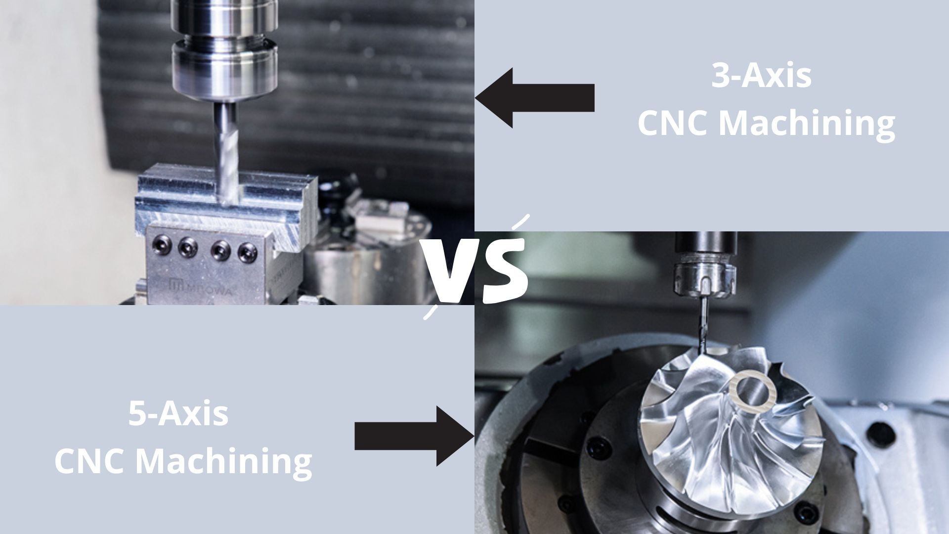
Explore the world of CNC machining as we compare 3-axis and 5-axis technologies. From basic operations to complex geometries, find out which machine suits your manufacturing needs in 2025.
Explore OPMT’s proven 5-phase ODM process for custom laser systems. ISO-certified manufacturing, ±0.003mm precision, IP protection. Submit project requirements today.
Looking for the best 5-axis CNC machining center suppliers? Check our top 10 list for expert insights and find the perfect fit for your needs!
Explore the top 10 laser metal cutting machines of 2025, featuring industry leaders like Trumpf, Bystronic, and OPMT Laser. Compare cutting-edge technology, precision, and efficiency to find the perfect solution for your manufacturing needs.
Please fill in your contact information to download the PDF.