Vereinbaren Sie einen Besuch
Egal ob Sie eine allgemeine Beratung oder spezifische Unterstützung benötigen, wir helfen Ihnen gerne weiter.
Egal ob Sie eine allgemeine Beratung oder spezifische Unterstützung benötigen, wir helfen Ihnen gerne weiter.
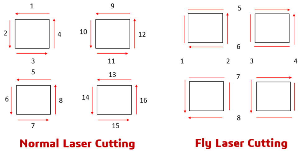
Herkömmliche Laserschneidsysteme verschwenden bis zu 401 TP3T Zykluszeit durch das Umpositionieren zwischen den Schnitten. Der Laserkopf stoppt, fährt zum nächsten Merkmal, stoppt erneut und wiederholt dieses Muster Hunderte oder Tausende Male pro Werkstück. Die Fly-Cut-Lasertechnologie beseitigt diese Ineffizienz durch kontinuierliche Optimierung des Bewegungspfads.
Der Unterschied ist offensichtlich: Anstatt an jeder Schnittposition anzuhalten, bewegt sich der Laserkopf kontinuierlich, während der Strahl synchron zur Bewegung ein- und ausgeschaltet wird. Für Hersteller, die Blechteile mit mehreren Bohrungen oder Merkmalen bearbeiten, bedeutet dies beim 30-50% einen höheren Durchsatz und messbar niedrigere Betriebskosten.
OPMT entwickelt 5-Achs- und Mehrachsen-CNC-Systeme Integriert mit ultraschneller Laserbearbeitungstechnologie. Unsere Systeme LP550V und LightMut 750V ermöglichen das Fliegenschneiden von superharten Materialien wie PKD, CBN und Hartlegierungen, bei denen herkömmliche Verfahren an ihre Grenzen stoßen. Dieser Leitfaden behandelt die technischen Grundlagen, praktischen Einschränkungen, Softwareanforderungen und Implementierungsaspekte der Fliegenschneid-Laserbearbeitung für Anwendungen in der Luft- und Raumfahrt, der Medizintechnik, der Automobilindustrie und im Präzisionswerkzeugbau.
Beim Fly Cutting handelt es sich um ein Bearbeitungsverfahren, bei dem sich der Laserkopf kontinuierlich bewegt und der Strahl entsprechend der Schnittlinie ein- und ausgeschaltet wird. Im Gegensatz zum herkömmlichen sequenziellen Schneiden, bei dem die Maschine an jedem Schnittpunkt anhält, wird beim Fly Cutting das gesamte Werkstück als kontinuierlicher Schnittweg behandelt.
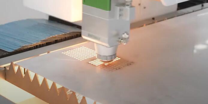
Das System analysiert die Geometrie des Werkstücks und plant eine optimierte Bearbeitungsroute – typischerweise ein Rastermuster aus horizontalen und vertikalen Schnittlinien. Bei der Bearbeitung eines Blechs mit 200 Löchern folgt der Laserkopf diesem vorgegebenen Pfad ohne Unterbrechung zwischen den einzelnen Elementen. Der Strahl schaltet sich ein, sobald der Kopf ein Element passiert, und in den Zwischenräumen wieder aus.
Die Pfadoptimierung ersetzt abrupte Winkeländerungen durch tangentiale Radiusübergänge. Anstatt dass der Kopf an 90-Grad-Ecken ruckartig die Richtung ändert, folgt er sanften Kurven, wodurch die mechanische Belastung von Führungsschienen und Lagern reduziert wird. Bei Systemen mit Linearmotoren verlängert dies die Lebensdauer der Komponenten durch die Verringerung der Spitzenbeschleunigungen.
Die Bezeichnung „Fly-Schneiden“ leitet sich vom Konzept der kontinuierlichen Bewegung ab – der Schneidkopf „fliegt“ über die Werkstückoberfläche, anstatt diskrete Start-Stopp-Bewegungen auszuführen. Manche Hersteller nennen dieses Verfahren Rasterschneiden, kontinuierliches Schneiden oder On-the-Fly-Bearbeitung. Gemeint ist jedoch immer dasselbe: synchronisierte Bewegung und Strahlsteuerung.
Herkömmliche sequentielle Schneidverfahren bearbeiten die Merkmale nacheinander: Loch 1 schneiden, Position wechseln, Loch 2 schneiden, Position wechseln, Loch 3 schneiden. Das Fliegenschneidverfahren hingegen bearbeitet die Merkmale in Serie: Es folgt einem optimierten Pfad und aktiviert den Strahl an den Lochpositionen 1, 2, 3, 4…200. Die Zeitersparnis summiert sich schnell bei Bauteilen mit Dutzenden oder Hunderten von Merkmalen.
Praxistests an OPMT-Systemen zeigen messbare Vorteile. Die Bearbeitung von 10.000 Löchern mit 0,5 mm Durchmesser in 1 mm dickem Edelstahl dauert mit sequenziellem Schneiden etwa 2,8 Stunden, mit Fliegenschneiden hingegen nur 1,4 Stunden – eine Reduzierung der Zykluszeit um 501 TP3T.
Die Bahnoptimierung beginnt mit einer Geometrieanalyse. Die Software untersucht die Bauteildatei, identifiziert alle Schnittmerkmale und ermittelt anschließend eine effiziente Abfolge, die die gesamte Verfahrstrecke minimiert. Bei Blechen mit verteilten Bohrungen ergibt sich typischerweise ein Rastermuster mit abwechselnden horizontalen und vertikalen Schnitten.
Der Algorithmus berücksichtigt mehrere Faktoren: die Gesamtweglänge, Richtungsänderungen, die Strahlaktivierungsfrequenz und das Wärmemanagement. Bereiche mit gehäuften Merkmalen erhalten andere Pfadstrategien als Bereiche mit gleichmäßig verteilten Merkmalen.
Die Laseraktivierung erfordert präzises Timing. Die CNC-Steuerung überwacht die tatsächliche Position des Schneidkopfes mittels einer geschlossenen Rückkopplungsschleife von Rasterskalen. Sobald der Kopf eine Bearbeitungsposition erreicht, sendet die Steuerung ein Signal zur Aktivierung des Lasers. Nach Abschluss der Bearbeitung wird der Laserstrahl deaktiviert. Dieser Vorgang wiederholt sich hunderte Male pro Minute beim Planfräsen.
Die Koordination mehrerer Achsen macht das Fliegenschneiden komplex. OPMT-Systeme integrieren Linearmotoren für die X/Y/Z-Achse mit direkt angetriebenen Drehachsen für die A/B/C-Positionierung. Linearmotoren beschleunigen schneller als Kugelgewindetriebe – unser Light 5X 40V erreicht eine Eilganggeschwindigkeit von 30 m/min bei einer Positioniergenauigkeit von ±0,005 mm.
Das geschlossene Regelsystem nutzt Gitterskalen, die eine Rückmeldung mit einer Auflösung von 0,001 mm ermöglichen. Die Steuerung vergleicht die Soll- mit der Ist-Position tausendfach pro Sekunde. Jede Abweichung löst eine Korrekturbewegung aus. Dadurch bleibt die Genauigkeit auch bei kontinuierlichen Hochgeschwindigkeitsbewegungen erhalten.
Die Modularisierung des Strahlpfads bedeutet, dass das Lasersystem als Plug-and-Play-Einheit konzipiert ist. OPMT-Systeme nutzen modulare Strahlpfade mit integrierten CCD-Positionierungskameras und hochpräzisen Sonden. Das modulare Design vereinfacht die Wartung und ermöglicht den Austausch verschiedener Laserquellen (Nanosekunden-, Pikosekunden- und Femtosekundenlaser) je nach Anwendungsanforderung.
Die Integration der CCD-Positionierung ermöglicht eine bildbasierte Überprüfung. Vor Beginn eines Schneidvorgangs erfasst das System ein Bild des Werkstücks, um die Ausrichtung zu überprüfen. Einige Bediener nutzen dies zur automatischen Offsetkorrektur bei der Bearbeitung mehrerer Teile mit geringfügigen Positionsabweichungen.
Die praktische Grenze liegt in der Synchronisationsgenauigkeit. Bei einer Schnittgeschwindigkeit von 20 m/min bewegt sich der Laserkopf mit 333 mm pro Sekunde. Eine um 0,001 Sekunden verzögerte Aktivierung des Lasers führt zu einem Positionsfehler von 0,33 mm. OPMT-Controller erreichen Reaktionszeiten im Submillisekundenbereich und halten Aktivierungsfehler unter 0,05 mm.
Bei komplexen Geometrien, die eine Rotation erfordern, koordiniert das System bis zu 5 Achsen gleichzeitig. Die LP550V bearbeitet polykristalline Diamant-Schneideinsätze (PCD) mit komplexen Winkeln, indem sie die A-Achse dreht, während die X-, Y- und Z-Achsen der Kontur folgen. Die Steuerung berechnet die inverse Kinematik in Echtzeit, um die korrekte Strahl-Werkstück-Beziehung aufrechtzuerhalten.
Die Zykluszeit verkürzt sich um 30–501 TP3T bei Bauteilen mit mehreren Merkmalen. Die genaue Reduzierung hängt von der Merkmalsdichte und dem Merkmalsabstand ab. Bauteile mit mehr als 100 Bohrungen erzielen die größten Einsparungen, da die Umpositionierungszeit bei herkömmlichen Bearbeitungsverfahren den größten Anteil ausmacht. Bauteile mit 10–20 großen Merkmalen weisen geringere Verbesserungen auf, da die Schnittzeit die Umpositionierungszeit übersteigt.
Die Energieeffizienz verbessert sich, da der Laserkopf nicht ständig beschleunigt und abbremst. Beschleunigung erfordert eine maximale Leistungsaufnahme der Antriebsmotoren. Kontinuierliche Bewegung mit gleichbleibender Geschwindigkeit verbraucht weniger Energie als wiederholte Start-Stopp-Zyklen. An einem typischen Produktionstag mit der Verarbeitung von 50 Bogen reduziert dies den Stromverbrauch um 12–181 TP3T.
Die Materialausnutzung wird durch Schnittfugenoptimierung verbessert. Das Fliegenschneiden ermöglicht flexiblere Verschachtelungsstrategien, da der Bahnplanungsalgorithmus beliebige Merkmalsfolgen verarbeiten kann. Herkömmliche Verschachtelungsmethoden hinterlassen oft unbrauchbare Reste zwischen den Teilen. Das Fliegenschneiden verarbeitet diese Reste ohne Zeitverlust und verbessert so die Materialausnutzung bei komplexen Verschachtelungslayouts um 15–251 TP3T.
Die Bildung von Materialresten wird reduziert. Beim herkömmlichen Schneiden entsteht bei jeder Bearbeitung ein Materialrest, der durch den Tisch fällt oder entfernt werden muss. Beim Fliegenschneiden können bestimmte Merkmale mit Mikro-Halterungen (kleinen Verbindungspunkten) bearbeitet werden, die die Materialreste bis zum Abschluss der Bearbeitung des gesamten Blechs fixieren. Dadurch wird das Risiko verringert, dass Materialreste während des Schneidens mit dem Laserkopf kollidieren.
Die Maschinenlebensdauer verlängert sich durch reduzierten Verschleiß an mechanischen Bauteilen. Linearführungen und Kugelgewindetriebe erfahren bei kontinuierlicher Bewegung im Vergleich zu wiederholten Start-Stopp-Zyklen eine geringere zyklische Belastung. OPMT-Systeme mit Planfräsen weisen basierend auf beschleunigten Verschleißtests eine um ca. 30% längere Lagerlebensdauer auf.
Die Teilequalität verbessert sich in manchen Anwendungen durch eine gleichmäßigere Wärmeverteilung. Sequenzielles Schneiden ermöglicht das vollständige Abkühlen jedes einzelnen Merkmals vor der Bearbeitung des nächsten. Beim Fliegenschneiden werden die Merkmale schnell nacheinander bearbeitet, was je nach Material und Dicke Vor- oder Nachteile haben kann. Bei dünnen Edelstahlblechen reduziert die kontinuierliche Wärmezufuhr den Verzug, indem lokale Spannungsspitzen vermieden werden.
Die ROI-Kennzahlen sind einfach. Ein Betrieb, der monatlich 1000 Teile mit jeweils 50 Merkmalen bearbeitet, spart durch die Reduzierung der Zykluszeit um 30% jährlich 700 Stunden. Bei einem Stundensatz von $75 entspricht dies einer wiedergewonnenen Kapazität von $52.500. Der Betrieb kann entweder das Volumen erhöhen oder die Überstundenkosten senken.
Durch den höheren Durchsatz können Aufträge, die zuvor erst am nächsten Tag fertiggestellt werden mussten, nun noch am selben Tag bearbeitet werden. Dies ist insbesondere für die Serienfertigung von Stanzwerkzeugen für die Automobilindustrie oder Trägern für Halbleiterbauteile von Bedeutung. Teile, deren Fertigung zuvor 8 Stunden dauerte, sind nun in 4–5 Stunden fertig, sodass zwei Chargen pro Schicht statt nur einer bearbeitet werden können.
Die Materialstärkebeschränkungen sind real. Das Fliegenschneiden eignet sich am besten für Materialien bis zu einer Dicke von 1,5 mm. Dickere Materialien erfordern geringere Schnittgeschwindigkeiten und höhere Laserleistungen, wodurch der Geschwindigkeitsvorteil des kontinuierlichen Schnitts eingeschränkt wird. Bei 3 mm dickem Edelstahl erzielt das herkömmliche Schneiden mit 2,5 m/min oft bessere Ergebnisse als das Fliegenschneiden mit 3,5 m/min, da die Strahlaktivierung schwieriger zu steuern ist.
Reflektierende Materialien erschweren das Fliegenschneiden. Edelstahl und Aluminium reflektieren 80–951 Tsd. ...
Komplexe Geometrien erfordern eine Zerlegung. Das Fliegenschneiden eignet sich am besten für Elemente, die sich als horizontale und vertikale Linien beschreiben lassen – Löcher, Schlitze, Rechtecke. Gekrümmte Elemente wie Kreisbögen mit kleinem Radius oder komplexe Splines lassen sich nicht sauber in Fliegenschneidepfade zerlegen. Daher ist ein hybrider Ansatz erforderlich: Einfache Elemente werden im Fliegenschneideverfahren bearbeitet, für komplexe Konturen wird auf den traditionellen Modus umgeschaltet.
Die Risiken der Wärmestauung sind materialspezifisch. Titanlegierungen und hochlegierte Nickel-Superlegierungen reagieren empfindlich auf Temperaturgradienten. Beim Fliegenschneiden erfolgen die Bearbeitungsschritte in schneller Folge, was zu Wärmestau an bestimmten Stellen führen kann. Dies beeinträchtigt die Materialintegrität durch Phasenübergänge oder Eigenspannungen. Für Bauteile in der Luft- und Raumfahrt, die eine vollständige Materialrückverfolgbarkeit erfordern, ist dies ein ernstzunehmendes Problem, das eine thermische Modellierung und Validierung notwendig macht.
Kollisionsvermeidung ist beim Planschneiden besonders wichtig. Bei einer Geschwindigkeit von 20 m/min bewegt sich der Laserkopf so schnell, dass eine Kollision mit einem schräg liegenden Werkstück die Optik beschädigen kann. Beim herkömmlichen Schneiden hat man Zeit, den korrekten Abwurf jedes Werkstücks zu überprüfen, bevor das nächste Element bearbeitet wird. Beim Planschneiden wird davon ausgegangen, dass alles einwandfrei abläuft. Die meisten Systeme verwenden Hochdruck-Hilfsgas (15–20 bar), um die Werkstücke durch den Tisch zu befördern. Dies funktioniert jedoch nicht bei allen Geometrien zuverlässig.
Es gibt Kompromisse bei der Genauigkeit. Traditionelle Schneidverfahren erreichen eine Positionsgenauigkeit von ±0,05 mm, da der Fräskopf während der Strahlaktivierung stationär ist. Beim Fliegenfräsen liegt die Genauigkeit bei ±0,1–0,15 mm, da sich der Fräskopf bei der Strahlaktivierung bewegt. Für Präzisionsanwendungen mit engen Toleranzen ist dies relevant. Komponenten medizinischer Implantate vertragen oft keine Positionsabweichung von 0,1 mm.
Die Schnittqualität variiert je nach Material und Dicke. Bei dünnen Materialien (0,5–1 mm) erzeugt das Planschneiden oft Schnittkanten, die mit herkömmlichen Schneidverfahren vergleichbar sind. Bei dickeren Materialien (2–3 mm) können die Rechtwinkligkeit der Schnittkante und die Oberflächenrauheit geringer sein, da der Strahl nicht lange genug verweilt, um die gesamte Materialstärke zu durchdringen, bevor er weiterfährt.
Die Softwarekomplexität steigt. Die CAM-Software muss Bahnplanung, Kollisionserkennung, thermische Simulation und Echtzeit-Bewegungssteuerung übernehmen. Nicht alle Laserschneidprogramme unterstützen das Fliegenschneiden, und diejenigen, die es unterstützen, erfordern Fachkenntnisse des Bedieners zur korrekten Parametereinstellung. Falsche Parameterwahl (zu hohe Schnittgeschwindigkeit, falsche Strahlumschaltfrequenz) führt zu Ausschuss.
CypCut bietet umfassende CAD/CAM-Funktionalität mit Positionsfehlerkorrektur durch zwei Antriebe. Die Software analysiert die Teilegeometrie und generiert automatisch Flugbahnen basierend auf benutzerdefinierten Parametern: maximale Sprungweite, Mikro-Tab-Größe und Rasterlinienabstand. Die Korrektur durch zwei Antriebe kompensiert das mechanische Spiel in Systemen mit Kugelgewindetrieben anstelle von Linearmotoren.
Die Benutzeroberfläche ermöglicht es dem Bediener, den Schnittpfad vor der Bearbeitung zu visualisieren. Sie sehen genau, wo der Laser aktiviert und deaktiviert wird, und können Parameter anpassen, falls der automatische Pfad fehlerhaft erscheint. Dadurch wird Material gespart, da Fehler bereits in der Simulation und nicht erst während der Produktion erkannt werden.
Cut Assist v2.0 von ANCA Motion verfolgt einen anderen Ansatz mit benutzerfreundlichen Steuerelementen, die keine CAM-Kenntnisse erfordern. Die Software bietet Schieberegler für Laserbreite (0,05–0,5 mm), Schnittgeschwindigkeit (1–30 m/min) und Strahlschaltfrequenz (1–10 kHz). Anwender passen diese Parameter je nach Materialart und -dicke an, ohne die zugrundeliegenden Bahnplanungsalgorithmen verstehen zu müssen.
Dies ist sinnvoll für Betriebe mit mehreren Mitarbeitern unterschiedlicher Qualifikationsstufen. Der leitende Programmierer legt die Basisparameter fest, anschließend nehmen die Mitarbeiter kleinere Anpassungen für spezifische Materialien oder Bauteilgeometrien vor. Die Software enthält eine Wissensdatenbank mit empfohlenen Einstellungen für gängige Material-/Dickenkombinationen.
HypCut optimiert Hochleistungslasersysteme (6–15 kW) hinsichtlich Schneidstrategie und Materialausnutzung. Die Software beinhaltet eine Nesting-Engine, die die Teile auf dem Blech so anordnet, dass die Gesamtschnittweglänge minimiert und gleichzeitig der korrekte Ein- und Auslaufabstand beibehalten wird. Dies ist insbesondere beim Fliegenschneiden entscheidend, da ein ineffizientes Nesting die Zeitersparnis durch kontinuierliche Bewegung zunichtemacht.
HypCut optimiert auch den Einsatz von Hilfsgas, was insbesondere bei der Serienfertigung wichtig ist. Die Kosten für Stickstoff-Hilfsgas liegen je nach lokalen Preisen zwischen 0,50 und 1,50 TP pro Blech. Optimierte Schnittwege reduzieren den Gasverbrauch durch kürzere Schnittzeiten und ein besseres Durchflussmanagement um 10 bis 15 TP.
Bahnplanungsalgorithmen nutzen verschiedene Techniken zur Optimierung des Flugfräsens. Intelligente Mikro-Laschen erzeugen 0,1–0,3 mm große Verbindungspunkte, die die Werkstücke während des Fräsens fixieren. Anschließend entnimmt der Bediener die fertigen Werkstücke durch Abbrechen der Laschen. Dadurch entfällt die Notwendigkeit von Werkstückhaltevorrichtungen bei verschachtelten Anordnungen.
Die Konfiguration der maximalen Sprungdistanz (1–5 mm) gibt der Software vor, wie weit der Kopf fahren kann, ohne den Pfad zu unterbrechen, bevor er neu berechnet werden soll. Kurze Sprungdistanzen führen zu effizienteren Pfaden für eng beieinander liegende Objekte. Lange Sprungdistanzen eignen sich besser für weit auseinander liegende Objekte, da hier das Zurückverfolgen mehr Zeit spart als eine zusätzliche Pfadkomplexität.
Durch präzise Steuerungsparameter wird eine Erkennungsgenauigkeit von 0,01 mm bei der Bestimmung von Überlappungen und Verbindungen von Merkmalen erreicht. Dies ist insbesondere bei Teilen mit tangentialen Merkmalen oder gemeinsamen Kanten wichtig. Die Software muss diese Beziehungen korrekt erkennen, um Doppelschnitte oder fehlende Kanten zu vermeiden.
OPMT-Systeme nutzen die CNC-Steuerung NEWCON IM 8, die über Standard-G-Code und proprietäre Erweiterungen mit CypCut, Cut Assist und HypCut kommuniziert. Die Steuerung interpoliert die Bewegung in Echtzeit – sie berechnet die X/Y/Z/A/B-Positionen 1000 Mal pro Sekunde, um eine gleichmäßige, kontinuierliche Bewegung zu gewährleisten und den Laser präzise zu aktivieren bzw. zu deaktivieren.
Manche Betriebe entwickeln kundenspezifische Postprozessoren, um die CAM-Ausgabe für ihre jeweiligen Maschinen zu optimieren. Dies erfordert Programmierkenntnisse, ermöglicht aber die Feinabstimmung von Beschleunigungsprofilen, Eckenrundung und Strahlumschaltzeiten basierend auf den tatsächlichen Maschinenfähigkeiten anstatt auf generischen Softwarevorgaben.
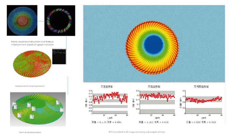
Die Luft- und Raumfahrtindustrie nutzt das Laser-Fliegenschneidverfahren zur Herstellung von PKD-Schneidwerkzeugen. Polykristalline Diamanteinsätze für die Bearbeitung von Aluminiumlegierungen erfordern eine präzise Schneidengeometrie mit Toleranzen von 0,02 mm. Die herkömmliche Funkenerosion benötigt 45–60 Minuten pro Einsatz. Die LP550V von OPMT verarbeitet diese Teile in 15-20 Minuten mittels Femtosekundenlaser-Fliegenschneiden mit gleichzeitiger 5-Achsen-Positionierung.
Die Bearbeitung von Turbinenschaufeln profitiert von der Fähigkeit des Planfräsens, komplexe, gekrümmte Oberflächen zu bearbeiten. Die Kühlbohrungen (0,3–0,8 mm Durchmesser) werden in zusammengesetzten Winkeln durch die Schaufeldicke positioniert. Die LP550V dreht das Werkstück um die A/B-Achse, während der Laserkopf dem optimierten Pfad folgt und 40–60 Bohrungen pro Schaufel in einer einzigen Aufspannung bearbeitet.
Die Fertigung von Leichtbaukomponenten aus Legierungen für Flugzeugstrukturen erfordert minimale Wärmeeinflusszonen. Femtosekundenlaser erzeugen nahezu keine thermischen Schäden, da die Pulsdauer für eine Wärmediffusion zu kurz ist. In Kombination mit der schnellen Bearbeitung beim Planfräsen ermöglicht dies das Bohren hunderter Präzisionslöcher in Aluminium-Lithium-Legierungsplatten ohne Verformung oder metallurgische Veränderungen.
Hersteller von Medizinprodukten verarbeiten Rohlinge für chirurgische Instrumente aus Edelstahl 440C und Titanlegierungen. Die Teile weisen verschiedene Merkmale auf – Schraubenlöcher, Schlitze zur Klingenbefestigung und ergonomisch geformte Kanten. Durch das Planfräsen lässt sich die Bearbeitungszeit pro Teil von 25 auf 12 Minuten reduzieren, was insbesondere bei der Fertigung von 500 bis 1000 Instrumenten von Bedeutung ist.
Die Bearbeitung implantierbarer Komponenten erfolgt mit biokompatiblen Materialien wie Ti-6Al-4V und Kobalt-Chrom-Legierungen. Diese Werkstoffe sind aufgrund von Kaltverfestigung konventionell schwer zu bearbeiten. Die Laserbearbeitung vermeidet mechanischen Kontakt, jedoch erzeugt das traditionelle sequentielle Schneiden thermische Gradienten, die die Materialeigenschaften verändern. Das Fliegenschneiden mit optimierten Strahlparametern gewährleistet eine gleichmäßige Wärmezufuhr über das gesamte Bauteil.
Automobilhersteller bearbeiten Batterieträgerkomponenten für Elektrofahrzeuge. Jeder Träger verfügt über 200 bis 400 Belüftungsöffnungen und Kabelführungsschlitze. Die Bearbeitungszeit beeinflusst die Produktionskapazität direkt. Die LightMut 750V von OPMT bearbeitet komplette Batterieträger in 8 bis 10 Minuten, im Vergleich zu 18 bis 22 Minuten bei herkömmlichen Verfahren.
Die Fertigung von Antriebskomponenten umfasst Zahnräder, Wellen und Montagehalterungen mit präzisen Lochmustern für die Montage. Teile aus gehärtetem Stahl erfordern Laserbearbeitung, da herkömmliche Bohrverfahren die Werkzeuge beschädigen. Das Planfräsen ermöglicht die Serienfertigung – Dutzende von Teilen pro Schicht – ohne Bedienereingriff.
Die Oberflächenstrukturierung von Automobil-Zierteilen erfolgt mittels Laserablation. Dabei werden spezifische Oberflächenmuster erzeugt, beispielsweise eine Ledermaserung oder ein gebürsteter Metalleffekt. Das Muster besteht aus Tausenden kleiner, abgetragener Strukturen. Das Gleitschneiden (Fly Cutting) ermöglicht eine schnellere Bearbeitung dieser Muster (40-50%) als die sequentielle Ablation.
Werkzeughersteller produzieren Hartmetall-Wendeschneidplatten mit komplexen Geometrien. Eine Wendeschneidplatte verfügt über mehrere Schneidkanten mit präziser Spanbrechergeometrie. Die Bearbeitung einer Charge von 100 Wendeschneidplatten dauert beim sequenziellen Schneiden 6–7 Stunden, im Vergleich zu 3,5–4 Stunden beim Planfräsen auf dem Light 5X 60V-System von OPMT.
Komplexe Schaftfräser mit unregelmäßigem Schneidenabstand und variablen Spiralwinkeln erfordern eine 5-Achs-Positionierung. Die LightMut 750V koordiniert das Laserschneiden mit der Rotationsachsenpositionierung, um diese Merkmale in einem einzigen Arbeitsgang zu fertigen.
Elektronikhersteller fertigen Präzisionsgehäuse für Smartphones und Tablets. Die Aluminiumgehäuse weisen Aussparungen für Tasten, Kameras, Lautsprecher und Anschlüsse auf. Jedes Gehäuse kann 20 bis 30 Bauteile enthalten, die enge Positionstoleranzen (±0,08 mm) erfordern. Das Planfräsen gewährleistet diese Toleranzen und erfüllt gleichzeitig die Produktionsanforderungen von über 10.000 Einheiten pro Tag.
Die Bearbeitung von Steckverbinderkomponenten umfasst kleine Stanzteile mit zahlreichen Bohrungen und Schlitzen. Die Teile haben eine Größe von 5–15 mm und Merkmale von nur 0,2 mm. Herkömmliche Verfahren stoßen bei diesen Abmessungen an ihre Grenzen. Laserschneiden hingegen bewältigt diese kleinen Dimensionen und erzeugt eine Kantenqualität, die für elektrische Kontaktflächen geeignet ist.
Für die Kühlkörperfertigung werden Kupfer oder Aluminium mit Lamellenstrukturen zur Wärmeableitung verwendet. Jeder Kühlkörper verfügt über 30 bis 80 Lamellen mit präzisem Abstand und exakter Höhe. Laserschneiden ermöglicht eine schnellere Herstellung der Lamellenstrukturen als Stanzen bei kleinen bis mittleren Stückzahlen (1.000 bis 10.000 Stück), und das Planschneiden macht die Fertigung wirtschaftlich, da sich die Bearbeitungszeit halbiert.
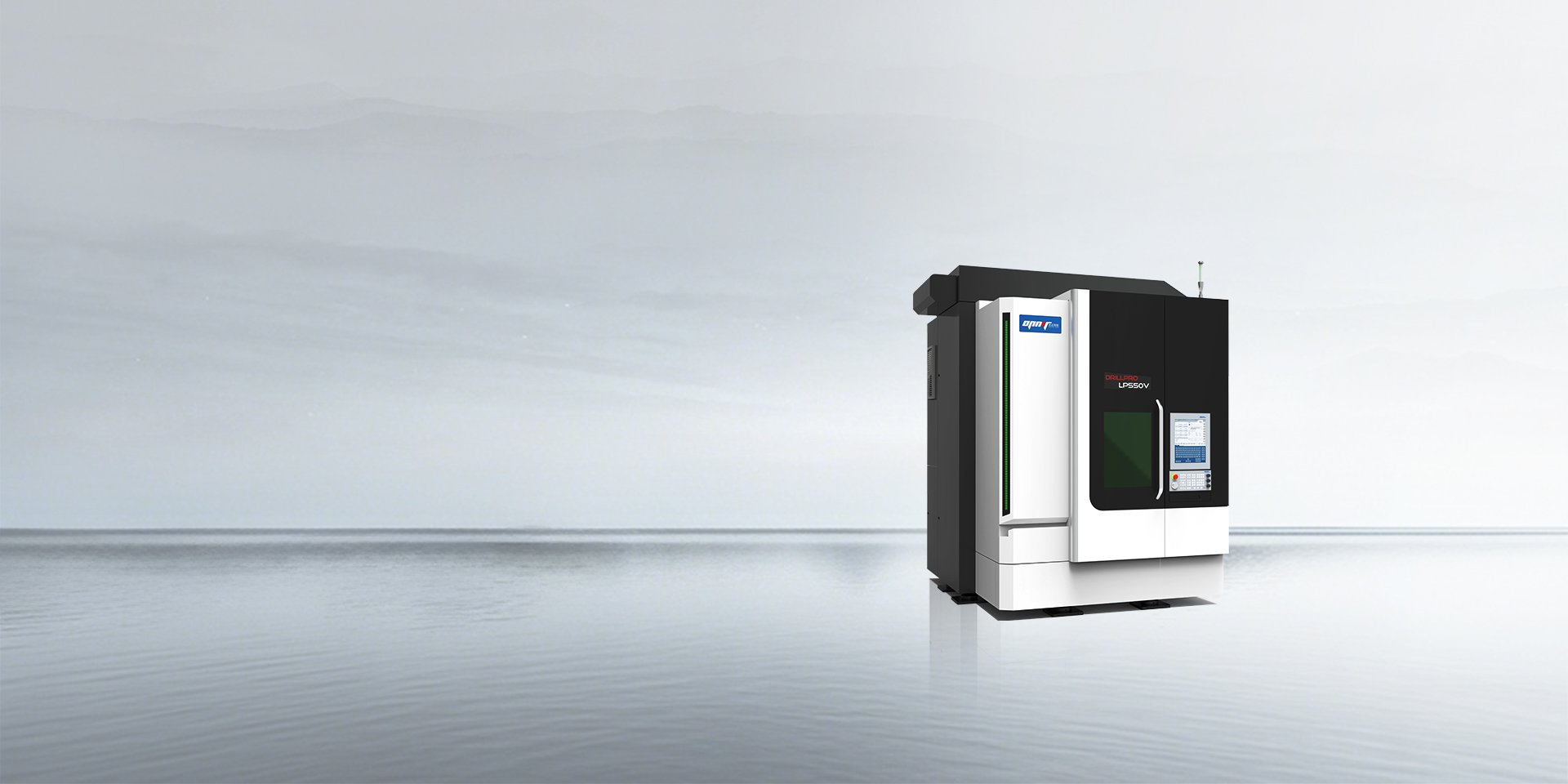
Die LP550V Fünf-Achs-Ultrakurzpulslaser-Rotationsschneidmaschine verarbeitet Femtosekunden- und Pikosekundenpulse mit einem Verfahrweg von 520 × 640 × 480 mm auf der X-, Y- und Z-Achse. Die Positioniergenauigkeit beträgt ±0,005 mm, die Wiederholgenauigkeit ±0,003 mm. Die A-Achse ermöglicht eine 360°-Drehung mit 100–200 U/min, während die C-Achse für Hochgeschwindigkeits-Indexierung mit 3500–6000 U/min rotiert.
Das System verwendet einen direkt angetriebenen Drehtisch mit 125 mm Durchmesser und eignet sich für Schneidwerkzeugeinsätze, medizinische Implantate und kleine Bauteile für die Luft- und Raumfahrt. Die maximale Tragfähigkeit beträgt 10 kg inklusive Spannvorrichtung. Als Laserquellen stehen Femtosekundenlaser (Pulsdauer < 500 fs) für Anwendungen ohne thermische Schädigung und Pikosekundenlaser (Pulsdauer 10–30 ps) für einen höheren Durchsatz bei weniger wärmeempfindlichen Materialien zur Verfügung.
Das LP550V verfügt über ein optisches Rotationsschneidmodul mit einem Eintrittspupillendurchmesser von 4,5 mm und wählbaren Brennweiten von 50 mm oder 60 mm. Damit lassen sich Bohrungsdurchmesser von 0,1 bis 1 mm mit Kegelwinkeln bis zu 6 Grad erzeugen. Das System erreicht ein Verhältnis von Bohrungstiefe zu Bohrungsdurchmesser von 15:1 und eignet sich daher für Kühlbohrungen in der Luft- und Raumfahrt sowie für Fluidkanäle in Medizingeräten.
Das LightMut 750V Laser-Schleif- und Fräszentrum vereint drei Laserquellen in einer Maschine: Nanosekundenlaser für allgemeine Schneidarbeiten, Pikosekundenlaser für Präzisionsarbeiten und Femtosekundenlaser für minimale thermische Belastung. Das System schaltet je nach programmiertem Arbeitsgang automatisch zwischen den Laserquellen um.
Der Verfahrweg beträgt 600 × 600 mm auf den X1/X2-Achsen (Doppelportal) und 600 mm auf der Y-Achse, bei einem Verfahrweg von 400 mm auf der Z-Achse. Der Arbeitstisch misst 500 × 500 mm und verfügt über M10-Gewindebohrungen im Abstand von 100 mm für flexible Spannvorrichtungen. Die Tragfähigkeit beträgt 200 kg für die gleichzeitige Bearbeitung mehrerer Teile.
Die LightMut 750V arbeitet mit Vorschubgeschwindigkeiten von 20–40 m/min und einer Positioniergenauigkeit von ±0,005 mm. Dank des Doppelportal-Designs können zwei Bereiche gleichzeitig unabhängig voneinander bearbeitet werden, wodurch sich der Durchsatz für bestimmte Werkstückgeometrien effektiv verdoppelt. Jedes Portal verfügt über eine eigene Z-Achse und ein eigenes Strahlführungssystem.
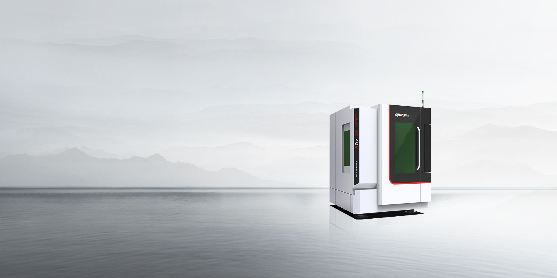
Das Light 5X 40V ist ein vertikales 5-Achs-Laserbearbeitungszentrum mit 400 mm Verfahrweg in der X-Achse, 250 mm in der Y-Achse und 300 mm in der Z-Achse. Das System nutzt Linearmotoren auf allen drei Achsen für schnelle Reaktionszeiten und hohe Positioniergenauigkeit. Lineare Rollenführungen zeichnen sich durch geringe Reibung und schnelle Beschleunigung aus – die Maschine erreicht eine Eilganggeschwindigkeit von 30 m/min.
Das Bett besteht aus Naturmarmor, der für thermische Stabilität und Vibrationsdämpfung sorgt. Marmor hat einen Wärmeausdehnungskoeffizienten von 8 × 10⁻⁶ pro °C, im Vergleich zu 12 × 10⁻⁶ bei Gusseisen. Dies bedeutet eine bessere Dimensionsstabilität bei langen Produktionsläufen.
Die Maschine verfügt über einen 100-W-Faserlaser mit HSK-E40- oder HSKA63-Spindelanschluss. Die B-Achse bietet einen Schwenkwinkel von 120° bei einer Nenndrehzahl von 100–150 U/min. Die C-Achse rotiert mit einer Nenndrehzahl von 200–300 U/min und einer maximalen Tragfähigkeit von 10 kg. Diese Konfiguration verarbeitet PKD-Werkzeugrohlinge, Hartmetall-Wendeschneidplatten und Keramikschneidwerkzeuge.
Light 5X 60V erweitert die X-Achse auf 600 mm bei gleichbleibendem Verfahrweg in Y- und Z-Richtung. Der größere Arbeitsbereich ermöglicht die Bearbeitung von Werkzeugen für die Automobilindustrie und die Fertigung größerer Bauteile für die Luft- und Raumfahrt. Das System ist mit Werkzeughaltern nach BT50 oder HSKA63 kompatibel und bietet eine maximale Tragfähigkeit von 40 kg in der C-Achse (einschließlich Spannvorrichtung).
Alle OPMT-Systeme nutzen eine geschlossene Gitterskalenrückmeldung mit einer Auflösung von 0,001 mm. Die CNC-Steuerung NEWCON IM 8 verarbeitet diese Rückmeldedaten mit einer Aktualisierungsrate von 1 kHz und ermöglicht so eine Positionskorrektur in Echtzeit während des Planfräsens.
Zu den technischen Spezifikationen gehören:
Das modulare Design ermöglicht die Anpassung an unterschiedliche Produktionsanforderungen. Strahlpfadmodul, CCD-Positionierungskamera und Tastmesssystem sind separate Baugruppen, die an der Z-Achse montiert werden. Bediener können verschiedene Laserquellen austauschen oder spezielle optische Konfigurationen hinzufügen, ohne die mechanische Struktur zu verändern.
Die Optimierung der Schnittparameter beginnt mit Materialtests. Verlassen Sie sich nicht auf generische Parameterdatenbanken – überprüfen Sie die Einstellungen an Ihren tatsächlichen Materialchargen. Edelstahl verschiedener Lieferanten kann einen deutlich unterschiedlichen Kohlenstoffgehalt aufweisen, was die Laserabsorption und das Schneidverhalten beeinflusst.
Die Schnittgeschwindigkeit lässt sich an die Materialstärke anpassen: Sie sinkt proportional zum Quadrat der Materialstärke. Schneidet man beispielsweise 1 mm Material mit 20 m/min, benötigt man für 2 mm Material nur noch 5 m/min, nicht 10 m/min. Der Laser muss tiefer eindringen und mehr Material abtragen, was exponentiell mehr Energie pro Längeneinheit erfordert.
Für das Fliegenschneiden sollte speziell die Strahlschaltfrequenz getestet werden. Schnellere Schaltzeiten (5–10 kHz) eignen sich gut für kleine Strukturen und dünne Materialien. Langsamere Schaltzeiten (1–3 kHz) sind besser für größere Strukturen und dickere Materialien geeignet, da sie dem Strahl eine Stabilisierung zwischen den Aktivierungen ermöglichen.
Die Konstruktion von Vorrichtungen für die Serienfertigung erfordert sorgfältige Planung. Die Vorrichtung muss die Werkstücke sicher fixieren, ohne den Laserstrahl zu behindern. Beim Planschneiden dürfen keine hohen Spannvorrichtungen oder Vorrichtungen verwendet werden, die über die Werkstückoberfläche hinausragen, da der sich kontinuierlich bewegende Laserkopf mit diesen kollidieren würde.
Vakuumvorrichtungen eignen sich hervorragend für flache Bleche. Das Werkstück liegt auf einem perforierten Tisch mit Vakuumzonen, die es während der Bearbeitung flach halten. Dies ermöglicht das Planschneiden mit minimalen Rüstzeiten zwischen den Teilen.
Die kundenspezifische Werkstückspannung für 3D-Teile erfordert die Abstimmung mit der Teilegeometrie. Die LP550V bearbeitet PKD-Wendeschneidplatten mithilfe einer Mehrteilvorrichtung, die bis zu 22 Teile gleichzeitig aufnehmen kann. Jedes Teil wird so positioniert und ausgerichtet, dass der Strahl während des Schneidvorgangs alle erforderlichen Merkmale erreichen kann.
Die Konfiguration des Hilfsgasdrucks verhindert das Aufeinanderprallen der Späne und gewährleistet saubere Schnitte. Für das Fliegenschneiden dünner Materialien (< 1,5 mm) wird ein Stickstoffdruck von 15–20 bar verwendet. Dieser ist höher als die üblicherweise beim sequenziellen Schneiden verwendeten 10–12 bar, da die Späne schneller abgeführt werden müssen.
Die Position der Gasdüse ist entscheidend. Stellen Sie den Düsenabstand auf 0,5–1 mm über der Werkstückoberfläche ein. Ist die Düse zu nah, trifft sie auf Materialreste. Ist sie zu weit entfernt, verflüchtigt sich der Gasdruck, bevor er die Schnittzone erreicht, was die Schnittqualität mindert.
Die Schnittreihenfolge wird typischerweise von links nach rechts und von oben nach unten definiert, um eine optimale Wärmeableitung zu gewährleisten. Die Bearbeitung aller Merkmale auf der linken Seite, bevor auf die rechte Seite gewechselt wird, führt zu einer besseren Wärmeableitung als ein Zickzack-Schnitt über das Werkstück.
Manche Werkstoffe profitieren von unterschiedlichen Bearbeitungsstrategien. Bei der Verarbeitung von Titanlegierungen erzielt man mit einem spiralförmigen Muster von außen nach innen oft bessere Ergebnisse als mit einem Gittermuster, da so die Bildung isolierter Heißzonen vermieden wird.
Wartungsprotokolle verlängern die Maschinenlebensdauer und erhalten die Genauigkeit. Linearführungsschienen müssen alle 500 Betriebsstunden mit ISO VG 68-Öl geschmiert werden. Geben Sie 2–3 Tropfen pro Schiene hinzu und bewegen Sie die Achsen über den gesamten Verfahrweg, um das Schmiermittel zu verteilen.
Die Reinigung optischer Komponenten ist für Lasersysteme unerlässlich. Überprüfen Sie die Fokussierlinse wöchentlich und reinigen Sie sie bei Verschmutzungen. Verwenden Sie Linsenreinigungslösung und optisches Reinigungstuch – berühren Sie die Linsenoberfläche niemals mit den Fingern oder Putzlappen.
Die Kalibrierungsintervalle hängen vom Produktionsvolumen ab. Betriebe mit hohem Produktionsvolumen (mehr als 16 Stunden täglicher Betrieb) sollten die Positioniergenauigkeit monatlich mithilfe eines Laserinterferometers oder eines Kugelstabsystems überprüfen. Betriebe mit geringem Produktionsvolumen können dies auf eine vierteljährliche Überprüfung ausdehnen.
Die Integration in bestehende Produktionsabläufe erfordert besondere Aufmerksamkeit hinsichtlich Dateiformaten und Datenübertragung. Die meisten CAD-Systeme exportieren DXF- oder STEP-Dateien. Ihre CAM-Software muss diese korrekt importieren und die Beziehungen der Elemente beibehalten. Testen Sie den gesamten Workflow, bevor Sie mit der Produktion beginnen.
Die CAD-Vorbereitung umfasst die Überprüfung, ob alle Elemente geschlossene Konturen ohne Lücken oder überlappende Linien aufweisen. Die CAM-Software kann keine korrekten Bearbeitungspfade generieren, wenn die Geometrie mehrdeutig oder fehlerhaft definiert ist.
Die nachgelagerte Qualitätskontrolle nutzt Koordinatenmessgeräte (KMG) oder optische Komparatoren zur Überprüfung der Merkmalspositionen. Die Ergebnisse werden dokumentiert und dem CAM-Programmierer zur Optimierung der Schnittparameter zurückgemeldet.
Die Bedienerschulung für die grundlegende Bedienung von Flugschneidanlagen dauert 40 bis 80 Stunden. Die Bediener müssen den Zusammenhang zwischen den Parametern der Bahnplanung und den tatsächlichen Schnittergebnissen verstehen. OPMT bietet eine einwöchige Vor-Ort-Schulung an. nach der Installation, einschließlich Inspektion, Betrieb, Programmierung und Fehlerbehebung.
Die Sicherheitsvorkehrungen für Laseranlagen der Klasse IV sind zwingend. Der Bearbeitungsbereich muss vollständig umschlossen sein und über verriegelte Türen verfügen, die den Laser beim Öffnen stoppen. Alle Bediener tragen Laserschutzbrillen, die für die jeweilige Wellenlänge geeignet sind (typischerweise OD 7+ für 1064 nm). Es sind klare Verfahren für die Sperrung und Kennzeichnung (Lockout/Tagout) während Wartungsarbeiten festzulegen.
Die Fly-Cut-Lasertechnologie ermöglicht messbare Verbesserungen bei Zykluszeit, Energieverbrauch und Materialausnutzung für Präzisionsfertigungsanwendungen. Die Reduzierung der Bearbeitungszeit durch das Modell 30-50% ist auch bei Bauteilen mit mehreren Merkmalen möglich, sofern das System korrekt konfiguriert ist und die Bediener die Zusammenhänge der Parameter verstehen.
Die Technologie ist nicht für alle Anwendungen geeignet. Dicke Materialien, komplexe, gekrümmte Geometrien und Teile, die eine Genauigkeit von ±0,05 mm erfordern, lassen sich besser mit dem herkömmlichen sequenziellen Schneidverfahren bearbeiten. Reflektierende Materialien erfordern eine sorgfältige Parameterentwicklung, um zuverlässige Ergebnisse zu erzielen.
Die Maschinen der Serien LP550V, LightMut 750V und Light 5X von OPMT vereinen das Planfräsen mit 5-Achs-Positionierung und ultraschnellen Laserquellen. Diese Systeme eignen sich für Anwendungen von PKD-Werkzeugen für die Luft- und Raumfahrt über Implantate für die Medizintechnik bis hin zu Komponenten für Automobilbatterien.
Die Implementierung erfordert die sorgfältige Auswahl der Software, die Konstruktion der Vorrichtung, die Optimierung der Parameter und die Schulung der Bediener. Die anfängliche Investition in eine korrekte Einrichtung zahlt sich durch höheren Durchsatz und geringere Betriebskosten aus.
Für Hersteller, die monatlich mehr als 1000 Teile mit jeweils über 20 Merkmalen bearbeiten, amortisiert sich das Planfräsen in der Regel innerhalb von 12 bis 18 Monaten durch höhere Kapazität und geringere Lohnkosten. Kontaktieren Sie das technische Team von OPMT, um Ihre spezifischen Anwendungsanforderungen zu besprechen und Materialtests auf unseren Systemen zu vereinbaren.
Haftungsausschluss
Dieser Inhalt wurde von OPMT Laser auf Grundlage öffentlich verfügbarer Informationen zusammengestellt und dient ausschließlich zu Referenzzwecken. Die Erwähnung von Marken und Produkten Dritter dient dem objektiven Vergleich und stellt keine kommerzielle Verbindung oder Billigung dar.
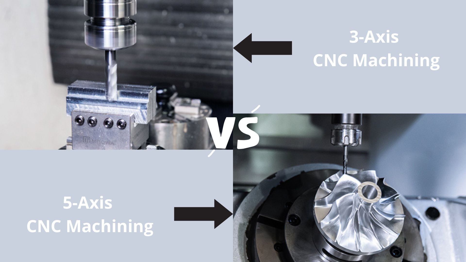
Entdecken Sie die Welt der CNC-Bearbeitung, indem wir 3-Achsen- und 5-Achsen-Technologien vergleichen. Von einfachen Vorgängen bis hin zu komplexen Geometrien – finden Sie heraus, welche Maschine Ihren Fertigungsanforderungen im Jahr 2025 entspricht.
Entdecken Sie OPMTs bewährten 5-Phasen-ODM-Prozess für kundenspezifische Lasersysteme. ISO-zertifizierte Fertigung, Präzision ±0,003 mm, IP-Schutz. Senden Sie uns noch heute Ihre Projektanforderungen.
Suchen Sie nach den besten Anbietern für 5-Achsen-CNC-Bearbeitungszentren? In unserer Top-10-Liste finden Sie Expertenwissen und die perfekte Lösung für Ihre Anforderungen!
Entdecken Sie die 10 besten Laser-Metallschneidmaschinen des Jahres 2025, darunter Branchenführer wie Trumpf, Bystronic und OPMT Laser. Vergleichen Sie Spitzentechnologie, Präzision und Effizienz, um die perfekte Lösung für Ihre Fertigungsanforderungen zu finden.
Bitte geben Sie Ihre Kontaktinformationen ein, um das PDF herunterzuladen.