Schedule a Visit
Regardless of whether you require general advice or specific support, we are happy to help you.
Regardless of whether you require general advice or specific support, we are happy to help you.
PCD (Polycrystalline Diamond) tool laser machining is a precise and efficient method for processing ultra-hard materials such as PCD, CBN, and CVD. This technology delivers sub-5 micron accuracy and superior edge quality with repeatability that surpasses traditional EDM and grinding. It enables manufacturers to increase throughput by up to three times and reduce per-part costs by 40-60%. This comprehensive guide presents detailed technical specifications, practical implementation guidelines, and troubleshooting strategies to support manufacturing professionals and laser system engineers.
PCD tool laser machining uses advanced five-axis CNC laser systems to process ultra-hard cutting tools with extreme precision and minimal heat distortion. The process ensures that cutting edges meet tight tolerances (under 5 microns) and retain sharp geometry without chipping or micro-cracking. As ultra-hard materials become standard in high-performance tooling, laser machining provides a competitive advantage by reducing cycle times and improving product consistency.

Key Takeaways:
Selecting the right laser machining system requires an understanding of key performance parameters related to mechanics, optics, and control systems.
| Specification | Light 5X 40V | Light 5X 60V | Micro3D L530V |
|---|---|---|---|
| Work Envelope (X×Y×Z) mm | 400 × 250 × 300 | 600 × 250 × 300 | 600 × 600 × 400 |
| Positioning Tolerance (mm) | 0.005 | 0.005 | 0.002 |
| Repeatability (mm) | 0.003 | 0.003 | 0.001 |
| Laser Type | 100 W Nanosecond Fiber | 100 W Nanosecond Fiber | 50–200 W Femtosecond (532/1064 nm) |
| Beam Quality (M²) | < 1.2 | < 1.2 | < 1.2 |
| CNC System | NUM / NewCon, RTCP | NUM / NewCon, RTCP | NewCon IM, AI Adaptive |
PCD tool laser machining significantly improves cycle times, surface quality, and cost-efficiency compared to EDM and grinding technologies.
| Metric | 5-Axis Laser Machining | EDM | Grinding |
|---|---|---|---|
| Cycle Time (Minutes) | ~5 | 20–30 | 15–25 |
| Surface Roughness (Ra) | <0.1 μm | 0.2–0.5 μm | 0.1–0.2 μm |
| Heat-Affected Zone | <1 μm | 20–50 μm | <5 μm |
| Per-Part Cost | Lower by 40–60% | Baseline | Moderate |
| Environmental Impact | Coolant-free, green | Coolant disposal | Abrasive dust |
Calculating the ROI for PCD tool laser machining investments involves assessing throughput gains, cost savings, and payback time.
Summary of ROI Calculation Steps:
Example:
PCD tool laser machining is deployable across industries including:
For further information, explore these in-depth resources:
Disclaimer
This content is compiled by OPMT Laser based on publicly available information for reference only; mentions of third-party brands and products are for objective comparison and do not imply any commercial association or endorsement.
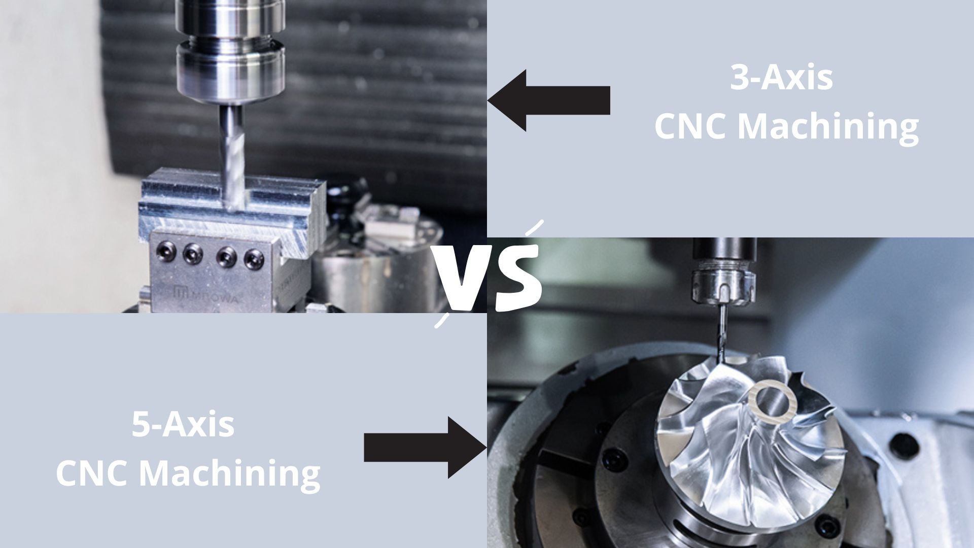
Explore the world of CNC machining as we compare 3-axis and 5-axis technologies. From basic operations to complex geometries, find out which machine suits your manufacturing needs in 2025.
Explore OPMT’s proven 5-phase ODM process for custom laser systems. ISO-certified manufacturing, ±0.003mm precision, IP protection. Submit project requirements today.
Looking for the best 5-axis CNC machining center suppliers? Check our top 10 list for expert insights and find the perfect fit for your needs!
Explore the top 10 laser metal cutting machines of 2025, featuring industry leaders like Trumpf, Bystronic, and OPMT Laser. Compare cutting-edge technology, precision, and efficiency to find the perfect solution for your manufacturing needs.
Please fill in your contact information to download the PDF.